
TM 5-2410-240-23-3
0197
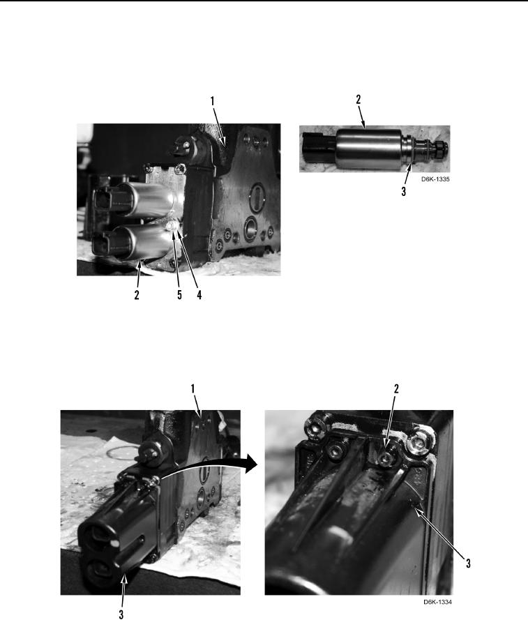
ASSEMBLY CONTINUED
16. Install four new O-rings (Figure 23, Item 3) on two solenoids (Figure 23, Item 2).
17. Install two solenoids (Figure 23, Item 2), clamps (Figure 23, Item 4), and bolts (Figure 23, Item 5) on blade
angle control valve (Figure 23, Item 1).
Figure 23. Solenoids.
0197
18. Install cover (Figure 24, Item 3) and three bolts (Figure 24, Item 2) on blade angle control valve
(Figure 24, Item 1).
Figure 24. Valve Solenoid Cover.
0197