
TM 5-2410-240-23-3
0197
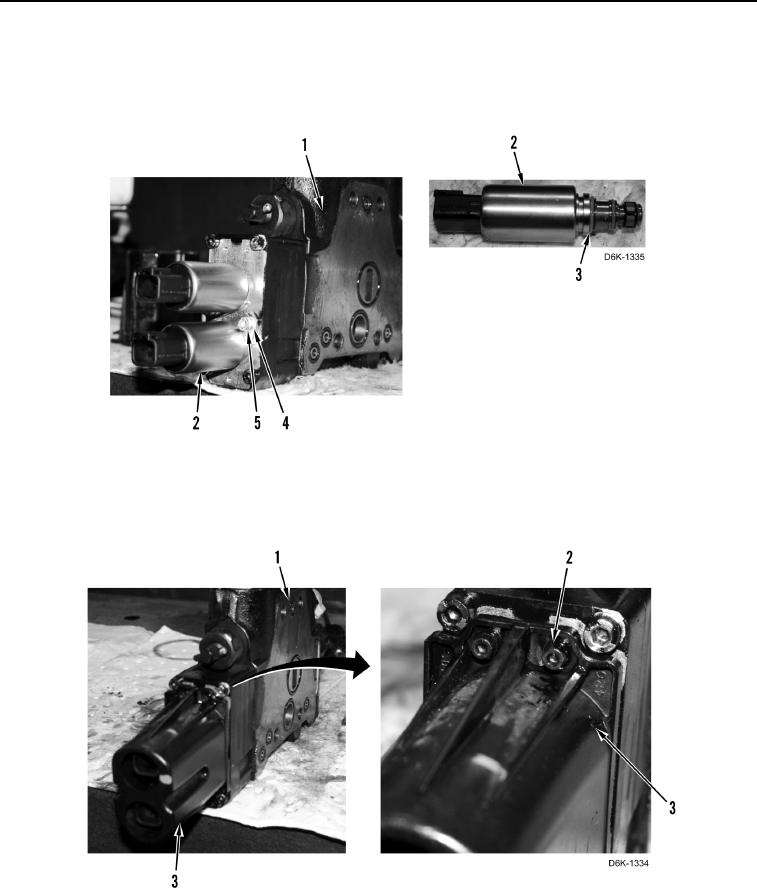
ASSEMBLY CONTINUED
10. Install four new O-rings (Figure 20, Item 3) on two solenoids (Figure 20, Item 2).
11. Install two solenoids (Figure 20, Item 2), clamps (Figure 20, Item 4), and bolts (Figure 20, Item 5) on blade lift
control valve (Figure 20, Item 1).
Figure 20. Solenoids.
0197
12. Install cover (Figure 21, Item 3) and three bolts (Figure 21, Item 2) on blade lift control valve
(Figure 21, Item 1).
Figure 21. Valve Solenoid Cover.
0197