
TM 5-2410-240-23-3
0197
DISASSEMBLY CONTINUED
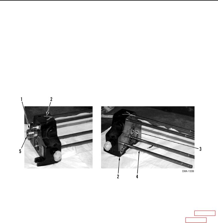
23. Remove four bolts (Figure 16, Item 4) from inlet manifold (Figure 16, Item 2).
N OT E
Note location and size of O-rings to aid installation.
24. Remove three fittings (Figure 16, Item 1) and six O-rings (Figure 16, Item 5) from inlet manifold
(Figure 16, Item 2). Discard O-rings.
N OT E
During removal, O-rings may stick to either side of valve face.
Note location and size of O-rings to aid installation.
25. Remove six O-rings (Figure 16, Item 3) from inlet manifold (Figure 16, Item 2). Discard O-rings.
Figure 16. Inlet Manifold.
0197
END OF TASK
CLEANING AND INSPECTION
000197
1. Clean and inspect all mechanical components IAW Mechanical General Maintenance Instructions (WP 0282).
2. Clean and inspect all electrical components IAW Electrical General Maintenance Instructions (WP 0283).
END OF TASK