
TM 5-2410-240-23-3
0197
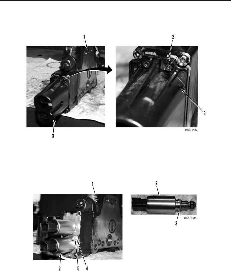
DISASSEMBLY CONTINUED
8. Remove three bolts (Figure 8, Item 2) and cover (Figure 8, Item 3) from blade angle control valve
(Figure 8, Item 1).
Figure 8. Valve Solenoid Cover.
0197
9. Remove two bolts (Figure 9, Item 5), clamps (Figure 9, Item 4), and solenoids (Figure 9, Item 2) from blade
angle control valve (Figure 9, Item 1).
10. Remove four O-rings (Figure 9, Item 3) from two solenoids (Figure 9, Item 2). Discard O-rings.
Figure 9. Solenoids.
0197