• Home
  • Download PDF
  • Order CD-ROM
  • Order in Print
Figure 3. Valve Bank Lines.
Figure 5. Valve Bank Assembly.

Field Maintenance Manual 3 D6K Dozer Type I With Winch and Type II With Ripper
Page Navigation
  223    224    225    226    227  228  229    230    231    232    233  
img
.
TM 5-2410-240-23-3
0197
REMOVAL CONTINUED
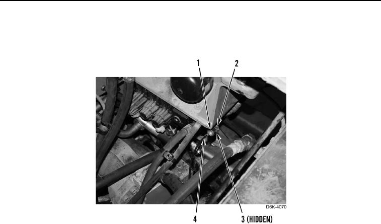
7. Loosen tube nut (Figure 4, Item 1) from fitting (Figure 4, Item 2).
8. Remove line (Figure 4, Item 4) and O-ring (Figure 4, Item 3) from fitting (Figure 4, Item 2). Discard O-ring.
Figure 4. Powertrain Diagnostic Line.
0197
0197-5


Privacy Statement
Press Release
Contact

© Copyright Integrated Publishing, Inc.. All Rights Reserved.