
TM 5-2410-240-23-3
0197
REMOVAL CONTINUED
WARN I N G
Use extreme caution when handling heavy parts. Provide adequate support and use
assistance during procedure. Failure to follow this warning may result in death or injury to
personnel.
WARN I N G
Hydraulic oil is very slippery. Immediately wipe up any spills. Failure to follow this warning
may cause injury to personnel.
N OT E
Note position and location of fittings to aid installation.
Valve bank weighs approximately 97 lb (44 kg).
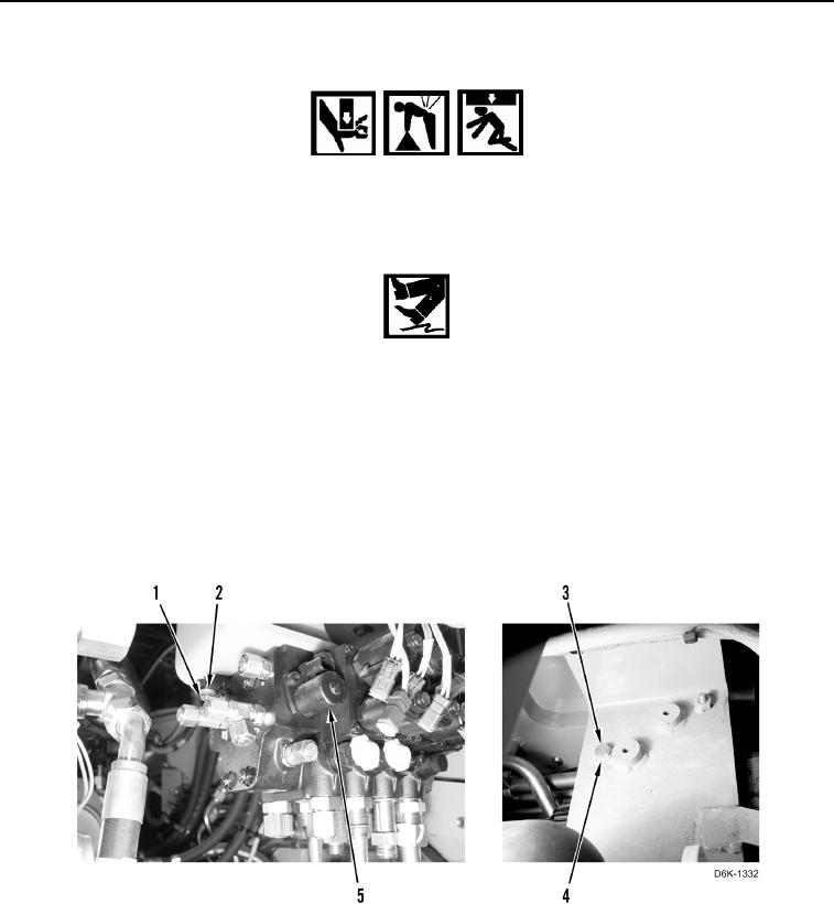
9. Remove two bolts (Figure 5, Item 1) and washers (Figure 5, Item 2) from valve bank (Figure 5, Item 5).
10. With assistance, remove bolt (Figure 5, Item 3), washer (Figure 5, Item 4), and valve bank (Figure 5, Item 5)
from machine.
Figure 5. Valve Bank Assembly.
0197
END OF TASK