
TM 5-2410-240-23-3
0197
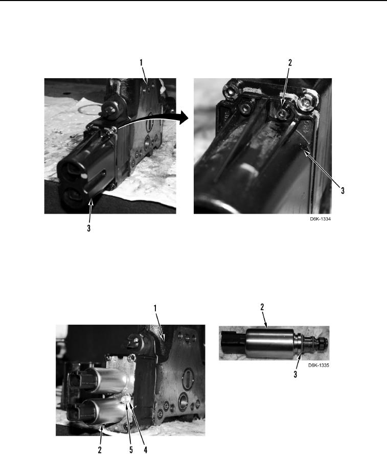
DISASSEMBLY CONTINUED
14. Remove three bolts (Figure 11, Item 2) and cover (Figure 11, Item 3) from blade tilt control valve
(Figure 11, Item 1).
Figure 11. Valve Solenoid Cover.
0197
15. Remove two bolts (Figure 12, Item 5), clamps (Figure 12, Item 4), and solenoids (Figure 12, Item 2) from blade
tilt control valve (Figure 12, Item 1).
16. Remove four O-rings (Figure 12, Item 3) from two solenoids (Figure 12, Item 2). Discard O-rings.
Figure 12. Solenoids.
0197