
TM 5-2410-240-23-3
0197
ASSEMBLY
000197
C AU T I O N
Install valves in correct order as noted during disassembly. Failure to follow this caution
may result in damage to equipment.
N OT E
Install O-rings as noted during removal.
1. Install six new O-rings (Figure 16, Item 3) on inlet manifold (Figure 16, Item 2).
2. Install six O-rings (Figure 16, Item 5) and three fittings (Figure 16, Item 1) on inlet manifold (Figure 16, Item 2).
3. Install four bolts (Figure 16, Item 4) on inlet manifold (Figure 16, Item 2).
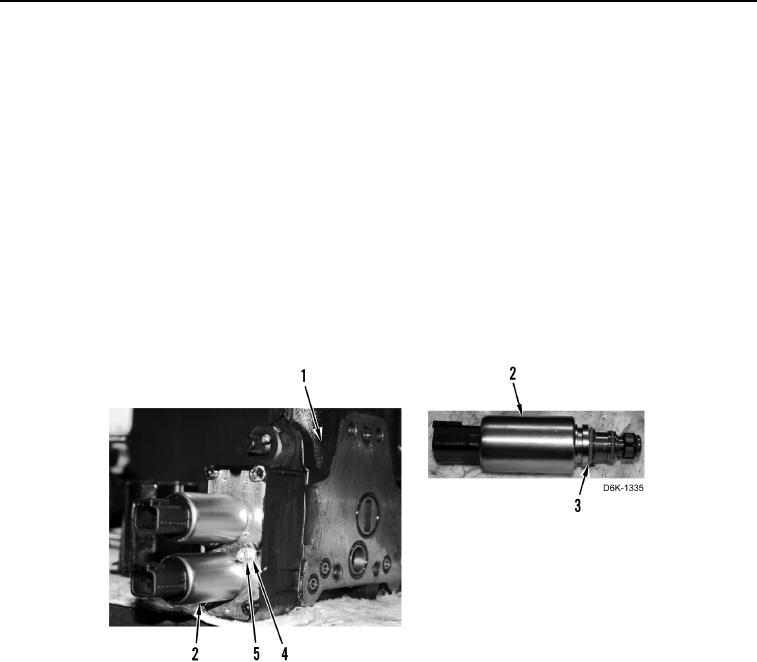
4. Install four new O-rings (Figure 17, Item 3) on two solenoids (Figure 17, Item 2).
5. Install two solenoids (Figure 17, Item 2), clamps (Figure 17, Item 4), and bolts (Figure 17, Item 5) on blade tilt
control valve (Figure 17, Item 1).
Figure 17. Solenoids.
0197