
TM 5-2410-240-23-3
0197
INSTALLATION CONTINUED
WARN I N G
Hydraulic oil is very slippery. Immediately wipe up any spills. Failure to follow this warning
may cause injury to personnel.
N OT E
Remove caps from ports for installation.
Install hoses and lines as noted during removal.
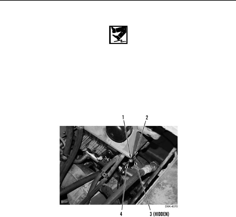
3. Install new O-ring (Figure 28, Item 3) on fitting (Figure 28, Item 2).
4. Install tube (Figure 28, Item 4) on fitting (Figure 28, Item 2).
5. Tighten tube nut (Figure 28, Item 1).
Figure 28. Powertrain Diagnostic Line.
0197