
TM 5-2410-240-23-3
0245
INSTALLATION CONTINUED
000245
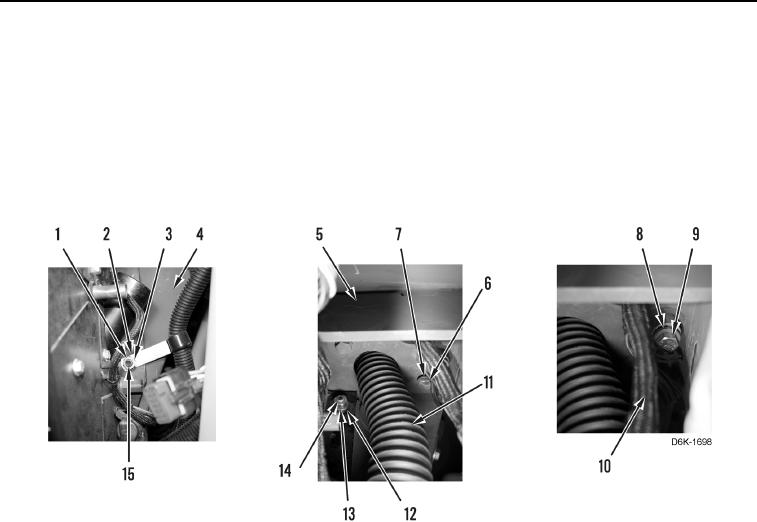
6. Install clamp (Figure 36, Item 2), washer (Figure 36, Item 3), and nut (Figure 36, Item 1) on stud (Figure 36,
Item 15).
7. Install washer (Figure 36, Item 12) and nut (Figure 36, Item 13) on stud (Figure 36, Item 14).
8. Install wiring harness (Figure 36, Item 10) and duct (Figure 36, Item 11) on bracket (Figure 36, Item 5).
9. Install bracket (Figure 36, Item 5), two washers (Figure 36, Item 7), and bolts (Figure 36, Item 6) on machine
(Figure 36, Item 4).
10. Install three ground straps (Figure 36, Item 8) and bolt (Figure 36, Item 9) on machine (Figure 36, Item 4).
Figure 36. Bracket, Duct, Wiring Harness, and Retaining Hardware On and Above A/C Heater Assembly.
0245