
TM 5-2410-240-23-3
0245
INSTALLATION CONTINUED
000245
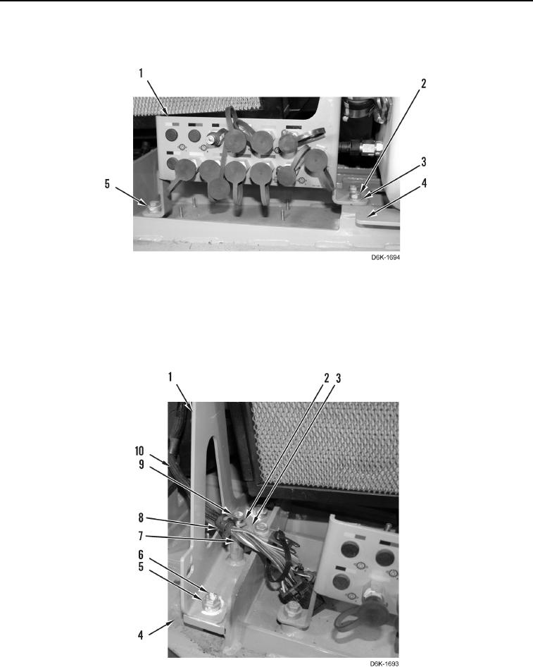
27. Install bracket (Figure 40, Item 1), spacer (Figure 40, Item 5), two washers (Figure 40, Item 3), and three bolts
(Figure 40, Item 2) on machine (Figure 40, Item 4).
Figure 40. Diagnostic Lines, Bracket, and Retaining Hardware Below A/C Heater Assembly.
0245
28. Install bracket (Figure 41, Item 1), two spacers (Figure 41, Item 5), and bolts (Figure 41, Item 6) on machine
(Figure 41, Item 4).
29. Position wiring harness (Figure 41, Item 10), and install spacer (Figure 41, Item 7), bracket (Figure 41, Item 3),
clip (Figure 41, Item 8), washer (Figure 41, Item 2), and bolt (Figure 41, Item 9) on bracket (Figure 41, Item 1).
Figure 41. Bracket and Retaining Hardware Below A/C Heater Assembly.
0245