
TM 5-2410-240-23-3
0245
INSTALLATION CONTINUED
000245
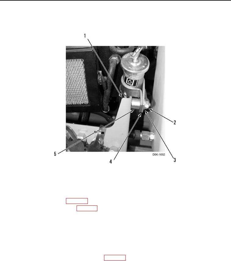
30. Install spacer (Figure 42, Item 5), clamp (Figure 42, Item 4), washer (Figure 42, Item 3), and nut (Figure 42,
Item 2) on bracket (Figure 42, Item 1).
Figure 42. Hydraulic Oil Filler Tube and Retaining Hardware Below A/C Heater Assembly.
0245
END OF TASK
FOLLOW-ON TASKS
000245
1. Install left rear access panel (WP 0193).
2. Install recirculation cabin air filter (WP 0252).
3. Refill engine coolant (WP 0043).
N OT E
When replacing evaporator, add 3 fl-oz (90 mL) of fresh refrigerant oil when recharging air
conditioning system. However, DO NOT add oil when replacing compressor and
evaporator at same time.
4. Evacuate and recharge air conditioning system (WP 0254).
5. Verify correct operation of machine (TM 5-2410-240-10).
END OF TASK
END OF WORK PACKAGE