• Home
  • Download PDF
  • Order CD-ROM
  • Order in Print
Figure 36. Bracket, Duct, Wiring Harness, and Retaining Hardware On and Above A/C Heater Assembly.
Figure 38. A/C Line, Orifice Tube, and O-rings on A/C Heater Assembly.

Field Maintenance Manual 3 D6K Dozer Type I With Winch and Type II With Ripper
Page Navigation
  765    766    767    768    769  770  771    772    773    774    775  
img
.
TM 5-2410-240-23-3
0245
INSTALLATION CONTINUED
000245
N OT E
Remove plugs or caps from hose and open port, and install hose as noted during removal.
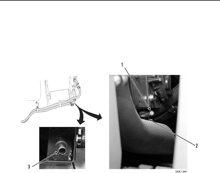
11. Loosely install clamp (Figure 37, Item 1) on connector hose (Figure 37, Item 2).
12. Connect connector hose (Figure 37, Item 2) on heater core (Figure 37, Item 3) and tighten clamp (Figure 37,
Item 1).
Figure 37. Connector Hose, Heater Core, and Clamp on Bottom of A/C Heater Assembly.
0245
0245-32


Privacy Statement
Press Release
Contact

© Copyright Integrated Publishing, Inc.. All Rights Reserved.