
TM 5-2410-240-23-3
0245
INSTALLATION CONTINUED
000245
N OT E
Remove plugs or caps from A/C lines and fittings and install A/C lines as noted during
removal.
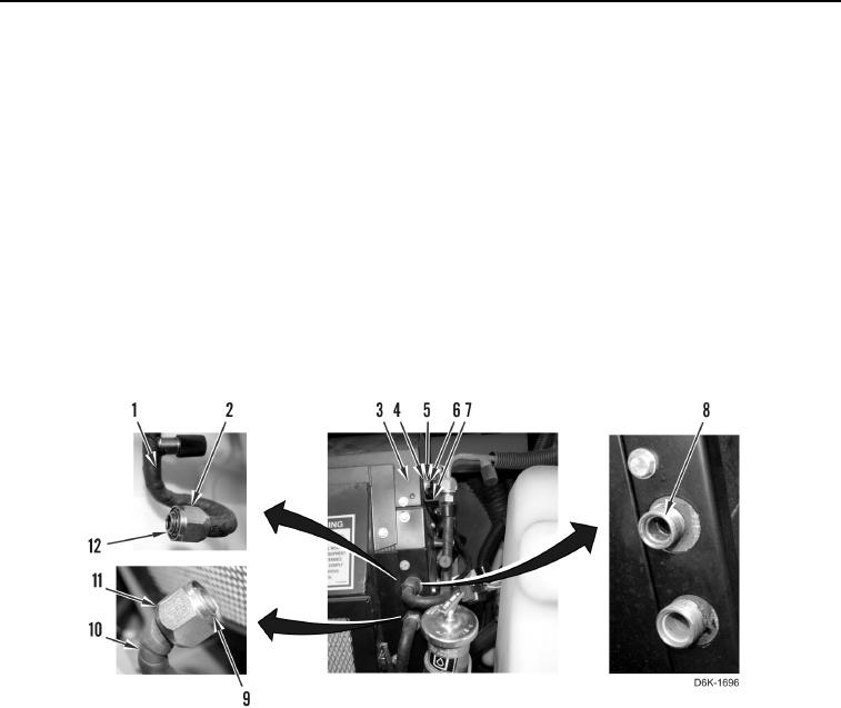
13. Apply refrigerant oil on new O-ring (Figure 38, Item 9) and install new O-ring on A/C line (Figure 38, Item 10).
14. Connect A/C line (Figure 38, Item 10) on evaporator core (Figure 38, Item 8) and tighten fitting (Figure 38,
Item 11).
15. Install new O-ring (Figure 38, Item 12) on orifice tube (Figure 38, Item 1).
16. Loosely connect orifice tube (Figure 38, Item 1) on evaporator core (Figure 38, Item 8).
17. Tighten fitting (Figure 38, Item 2).
18. Install bracket (Figure 38, Item 7), clip (Figure 38, Item 4), washer (Figure 38, Item 5), and bolt (Figure 38,
Item 6) on A/C heater assembly (Figure 38, Item 3).
Figure 38. A/C Line, Orifice Tube, and O-rings on A/C Heater Assembly.
0245