
TM 5-2410-240-23-3
0245
INSTALLATION CONTINUED
000245
N OT E
Remove plugs or caps from hose and open port, and install hose and harness connectors
as noted during removal.
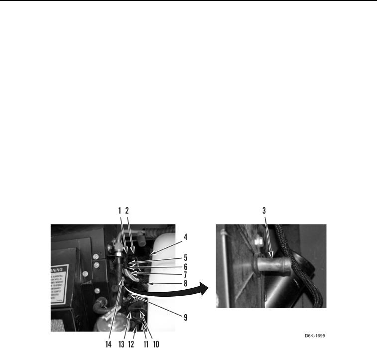
19. Connect harness connector (Figure 39, Item 11) on actuator (Figure 39, Item 12).
20. Connect and lock harness connector (Figure 39, Item 10) on temperature sensor (Figure 39, Item 13).
21. Loosely install clamp (Figure 39, Item 14) on upper heater hose (Figure 39, Item 8).
22. Connect upper heater hose (Figure 39, Item 8) on heater core (Figure 39, Item 3) and tighten clamp (Figure 39,
Item 14).
23. Loosely install clamp (Figure 39, Item 7) on duct hose (Figure 39, Item 4).
24. Connect duct hose (Figure 39, Item 4) on duct connector (Figure 39, Item 9) and tighten clamp (Figure 39,
Item 7).
25. Connect and lock harness connector (Figure 39, Item 6) on A/C heater assembly harness connector
(Figure 39, Item 5).
26. Connect and lock harness connector (Figure 39, Item 2) on temperature sensor (Figure 39, Item 1).
Figure 39. Harness Connectors, Upper Heater Hose, Duct, and Clamps on A/C Heater Assembly.
0245