
TM 5-2410-240-23-3
0261
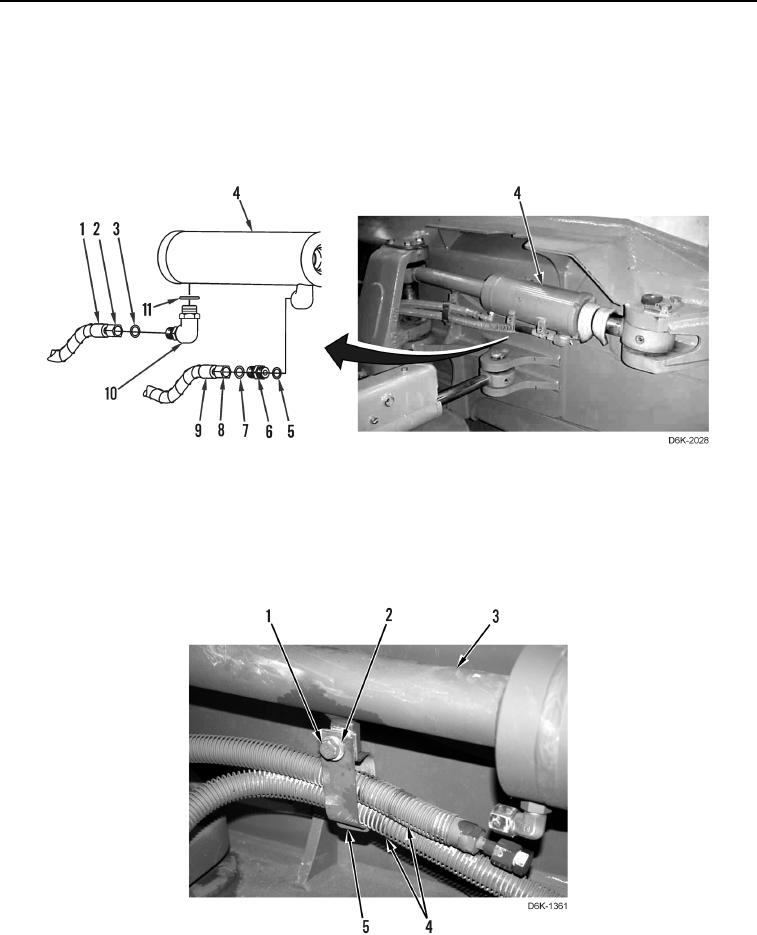
DISASSEMBLY CONTINUED
3. Loosen two fittings (Figure 2, Items 2 and 8) and disconnect hydraulic hoses (Figure 2, Items 1 and 9) from
connectors (Figure 2, Items 6 and 10). Position hydraulic hoses aside.
4. Remove two O-rings (Figure 2, Items 3 and 7) from connectors (Figure 2, Items 6 and 10). Discard O-rings.
5. Remove two connectors (Figure 2, Items 6 and 10) from cylinder (Figure 2, Item 4).
6. Remove two O-rings (Figure 2, Items 5 and 11) from connectors (Figure 2, Items 6 and 10). Discard O-rings.
Figure 2. Hydraulic Hoses.
0261
7. Remove bolt (Figure 3, Item 1), washer (Figure 3, Item 2), and two clamp brackets (Figure 3, Item 5) from
cylinder (Figure 3, Item 3).
8. Remove two clamp brackets (Figure 3, Item 5) from hydraulic hoses (Figure 3, Item 4). Position hydraulic
hoses aside.
Figure 3. Hydraulic Hoses Clamp Brackets.
0261