
TM 5-2410-240-23-3
0261
DISASSEMBLY CONTINUED
WARN I N G
Cylinders can remain pressurized for longperiods, even with hydraulic hoses removed.
Relieve pressure before disassembling cylinder.
Lubricating/hydraulic oils used in performa ce of maintenance can be very slippery.
n
Immediately wipe up any spills.
Failure to follow these warnings may result in injury or death to personnel.
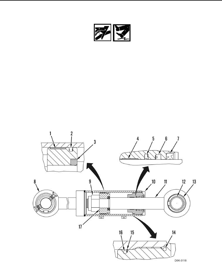
12. Loosen head (Figure 5, Item 10).
13. Remove rod (Figure 5, Item 11) and head (Figure 5, Item 10) from cylinder housing (Figure 5, Item 8).
N OT E
Note position of piston to aid installation.
14. Remove locknut (Figure 5, Item 9), piston (Figure 5, Item 17), washer (Figure 5, Item 3), and head (Figure 5,
Item 10) from rod (Figure 5, Item 11). Discard locknut.
Figure 5. Tilt Cylinder, Head, Rod, Bearings, and Internal Components.
0261