
TM 5-2410-240-23-3
0261
DISASSEMBLY CONTINUED
WARN I N G
Use extreme caution when handling heavy parts. Provide adequate support and use
assistance during procedure. Ensure any lifting device used is in good condition and of
suitable load capacity. Keep clear of heavy parts supported only by lifting device. Failure
to follow this warning may result in injury or death to personnel.
N OT E
Tilt cylinder weighs approximately 150 lb (68 kg).
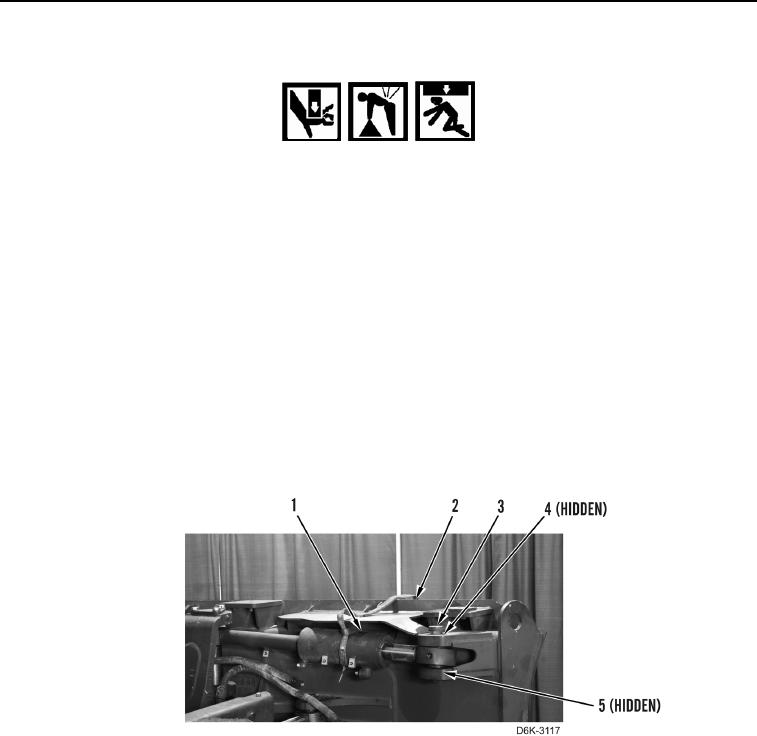
9. Attach lifting device on tilt cylinder (Figure 4, Item 1).
N OT E
Note position and orientation of spacers to aid installation.
10. Remove pin (Figure 4, Item 3) and two spacers (Figure 4, Items 4, and 5) from retaining tilt cylinder (Figure 4,
Item 1) and blade (Figure 4, Item 2).
11. Using lifting device and assistance, remove tilt cylinder (Figure 4, Item 1) from blade (Figure 4, Item 2).
Figure 4. Tilt Cylinder and Retaining Hardware.
0261
END OF TASK