
TM 5-2410-240-23-3
0261
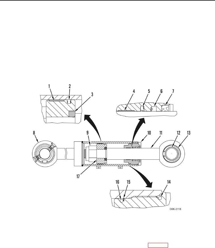
DISASSEMBLY CONTINUED
N OT E
Note position and location of seals and rings to aid installation.
15. Remove wiper seal (Figure 6, Item 7), U-cup seal (Figure 6, Item 6), buffer seal (Figure 6, Item 5), wear ring
(Figure 6, Item 4), two O-ring seals (Figure 6, Items 14 and 16), and backup ring (Figure 6, Item 15) from head
(Figure 6, Item 10). Discard all seals and rings.
16. Remove seal (Figure 6, Item 2) and ring (Figure 6, Item 1) from piston (Figure 6, Item 17). Discard seal and
ring.
17. Remove retaining ring (Figure 6, Item 13) and bearing (Figure 6, Item 12) from rod (Figure 6, Item 11). Discard
retaining ring and bearing.
Figure 6. Tilt Cylinder, Head, Rod, Bearings, and Internal Components.
0261
END OF TASK
CLEANING AND INSPECTION
000261
Clean and inspect all parts IAW Mechanical General Maintenance Instructions (WP 0282).
END OF TASK