
TM 5-2410-240-23-3
0261
ASSEMBLY CONTINUED
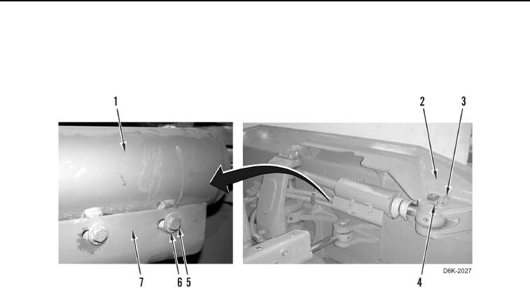
12. Install guard (Figure 10, Item 7), two washers (Figure 10, Item 6), and bolts (Figure 10, Item 5) on tilt cylinder
(Figure 10, Item 1).
13. Install retainer (Figure 10, Item 4) and two bolts (Figure 10, Item 3) on blade (Figure 10, Item 2).
Figure 10. Tilt Cylinder, Guard, and Retaining Hardware.
0261
END OF TASK
FOLLOW-ON TASKS
000261
1. Check hydraulic oil level (WP 0160).
2. Verify correct operation of machine (TM 5-2410-240-10).
END OF TASK
END OF WORK PACKAGE
0261-11/(12 blank)