
TM 5-2410-240-23-3
0262
REMOVAL CONTINUED
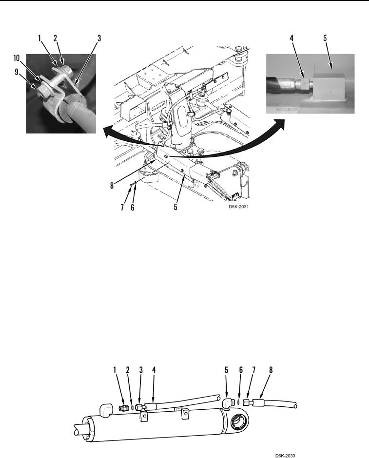
Figure 1. Angle Cylinder, Bracket, Lubrication Hose, and Retaining Hardware.
0262
C AU T I O N
Cap or plug all hydraulic hose ends and fittings during removal to protect against
contamination. Failure to follow this caution may result in damage to equipment.
N OT E
Tag and mark hydraulic hoses and fittingsand note hose routing to aid installation.
Use a container to catch any fluid that maydrain from hydraulic system. Dispose of fluid
IAW local policy and ordinances. Ensure all spills are cleaned up.
5. Loosen two fittings (Figure 2, Items 3 and 7) and disconnect hydraulic hoses (Figure 2, Items 4 and 8) from
connectors (Figure 2, Items 1 and 5). Position hydraulic hoses aside.
6. Remove two O-rings (Figure 2, Items 2 and 6) from connectors (Figure 2, Items 1 and 5). Discard O-rings.
Figure 2. Hydraulic Hoses.
0262