
TM 5-2410-240-23-3
0262
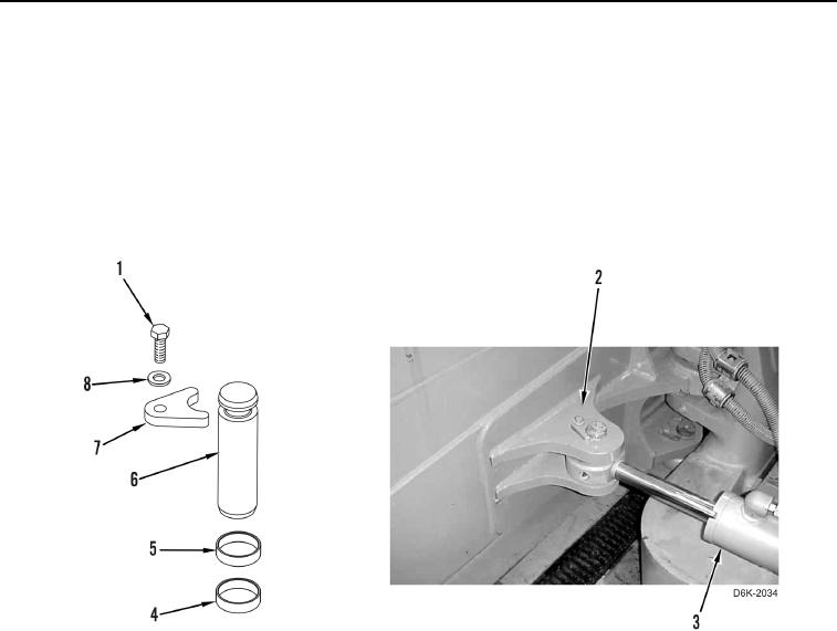
REMOVAL CONTINUED
7. Attach lifting device on angle cylinder (Figure 3, Item 3).
N OT E
Note position of spacers.
8. Remove bolt (Figure 3, Item 1), washer (Figure 3, Item 8), retainer (Figure 3, Item 7), pin (Figure 3, Item 6),
and two spacers (Figure 3, Items 5 and 4), retaining angle cylinder (Figure 3, Item 3) on blade (Figure 3,
Item 2).
Figure 3. Angle Cylinder Retaining Hardware on Blade.
0262
N OT E
Note position of spacers.
9. Remove three bolts (Figure 4, Item 4), retainer (Figure 4, Item 5), pin (Figure 4, Item 6), and two spacers
(Figure 4, Items 7 and 8), retaining angle cylinder (Figure 4, Item 10) on frame (Figure 4, Item 9).
10. Position angle cylinder (Figure 4, Item 10) forward.
11. Loosen fitting (Figure 4, Item 2) and disconnect lubrication hose (Figure 4, Item 1) from connector (Figure 4,
Item 3). Remove lubrication hose from machine.