
TM 5-2410-240-23-3
0261
ASSEMBLY CONTINUED
N OT E
Remove caps and plugs beforeinstalling hydraulic hose.
Install hydraulic hoses as noted during removal.
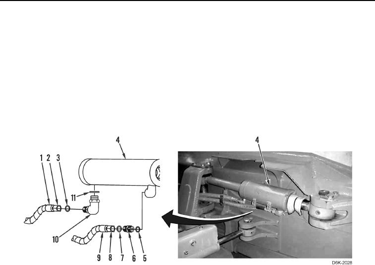
8. Install two new O-rings (Figure 9, Items 11 and 5) on connectors (Figure 9, Items 10 and 6).
9. Install two connectors (Figure 9, Items 10 and 6) on cylinder (Figure 9, Item 4).
10. Install two new O-rings (Figure 9, Items 7 and 3) from connectors (Figure 9, Items 10 and 6).
11. Connect two hydraulic hoses (Figure 9, Items 9 and 1) on connectors (Figure 9, Items 10 and 6) and tighten
fittings (Figure 9, Items 8 and 2).
Figure 9. Hydraulic Hoses.
0261