• Home
  • Download PDF
  • Order CD-ROM
  • Order in Print
Figure 7. Tilt Cylinder and Retaining Hardware.
Figure 9. Hydraulic Hoses.

Field Maintenance Manual 3 D6K Dozer Type I With Winch and Type II With Ripper
Page Navigation
  938    939    940    941    942  943  944    945    946    947    948  
img
.
TM 5-2410-240-23-3
0261
ASSEMBLY CONTINUED
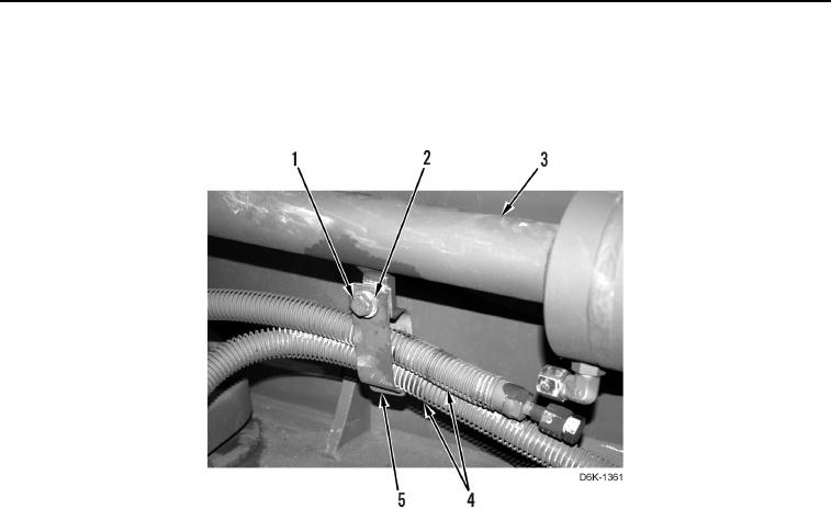
6. Install two clamp brackets (Figure 8, Item 5) on hydraulic hoses (Figure 8, Item 4).
7. Install two clamp brackets (Figure 8, Item 5), washer (Figure 8, Item 2), and bolt (Figure 8, Item 1) on cylinder
(Figure 8, Item 3).
Figure 8. Hydraulic Hoses Clamp Brackets.
0261
0261-9


Privacy Statement
Press Release
Contact

© Copyright Integrated Publishing, Inc.. All Rights Reserved.