
TM 5-2410-240-23-3
0267
REMOVAL CONTINUED
N OT E
Note location of tiedown sraps to aid installation.
t
Tag and mark electrical connectors to aid installation.
Tag and mark hoses and fittings to aid installation.
Use a container to catch any fluid that may drain from hoses or system. Dispose of fluid
IAW local policy and ordinances. Ensure all spills are cleaned up.
Cap or plug hoses, fittings, and open ports.
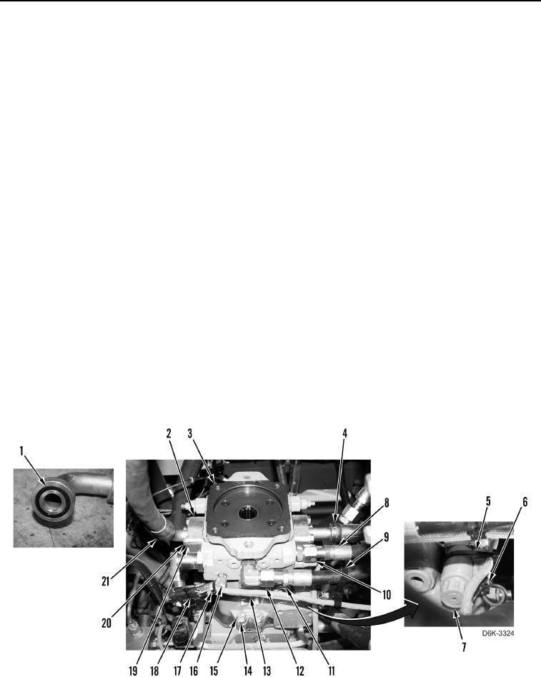
3. Remove tiedown strap (Figure 2, Item 9) from hose (Figure 2, Item 11). Discard tiedown strap.
4. Loosen tube nut (Figure 2, Item 12) and disconnect hose (Figure 2, Item 11) from winch piston pump (Figure 2,
Item 3). Position hose aside.
5. Loosen tube nut (Figure 2, Item 10) and disconnect hose (Figure 2, Item 8) from winch piston pump (Figure 2,
Item 3). Position hose aside.
6. Remove tiedown straps (Figure 2, Item 17) from fitting (Figure 2, Item 16), sensor (Figure 2, Item 18), and
harness (Figure 2, Item 13). Discard tiedown straps.
7. Disconnect harness (Figure 2, Item 13) from sensor (Figure 2, Item 18).
8. Remove tiedown strap (Figure 2, Item 5) from solenoid (Figure 2, Item 7) and harness (Figure 2, Item 6).
Discard tiedown strap.
9. Disconnect harness (Figure 2, Item 6) from solenoid (Figure 2, Item 7). Position harness aside.
10. Remove eight bolts (Figure 2, Item 20), washers (Figure 2, Item 19), four clamps (Figure 2, Item 2), and two
hoses (Figure 2, Items 21 and 4) from winch piston pump (Figure 2, Item 3).
11. Remove two O-rings (Figure 2, Item 1) from hoses (Figure 2, Items 21 and 4). Discard O-rings. Position hoses
aside.
12. Remove two bolts (Figure 2, Item 15) and spacers (Figure 2, Item 14) from winch piston pump
(Figure 2, Item 3).
INSERT ART D6K-3324
Figure 2. Harness, Solenoid, Hoses, and Retaining Hardware on Winch Piston Pump.
0267