
TM 5-2410-240-23-3
0266
INSTALLATION
000266
N OT E
Remove caps or plugs from hydraulic hoses and fittings and install hydraulic hoses and
fittings as noted during removal.
Install electrical harness as noted during removal.
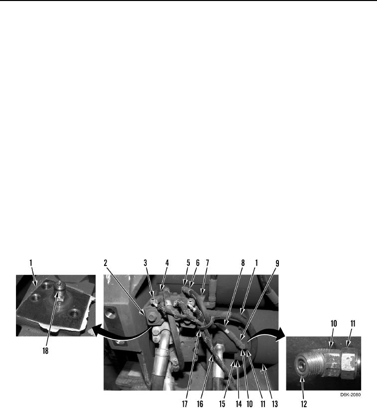
1. Apply lubricating oil on two new O-rings (Figure 5, Items 18 and 12).
2. Install new O-ring (Figure 5, Item 18) on motor assembly (Figure 5, Item 1).
3. Install winch manifold (Figure 5, Item 7) and three bolts (Figure 5, Item 4) on motor assembly (Figure 5,
Item 1).
4. Rotate motor assembly (Figure 5, Item 1) counterclockwise.
5. Install four washers (Figure 5, Item 14) and bolts (Figure 5, Item 15) retaining motor assembly (Figure 5,
Item 1) on winch (Figure 5, Item 13).
6. Connect five winch hoses (Figure 5, Item 8) on fittings (Figure 5, Item 5) and tighten fasteners (Figure 5,
Item 6).
7. Install new O-ring (Figure 5, Item 12) on fittings (Figure 5, Item 10).
8. Rotate fitting (Figure 5, Item 10) counterclockwise and tighten nut (Figure 5, Item 11).
9. Connect winch hose (Figure 5, Item 8) on fitting (Figure 5, Item 10) and tighten fastener (Figure 5, Item 9).
10. Connect three electrical connectors (Figure 5, Item 3) on solenoids (Figure 5, Item 2).
11. Install new tiedown strap (Figure 5, Item 17) on winch harness (Figure 5, Item 16) and winch hose (Figure 5,
Item 8).
Figure 5. Winch Manifold, Fittings, O-rings, and Retaining Hardware.
0266