
TM 5-2410-240-23-3
0266
DISASSEMBLY
000266
C AU T I O N
Cap or plug all fittings and ports during removal to protect against contamination. Failure
to follow this caution may result in damage to equipment.
N OT E
Note orientation of fittings to aid installation.
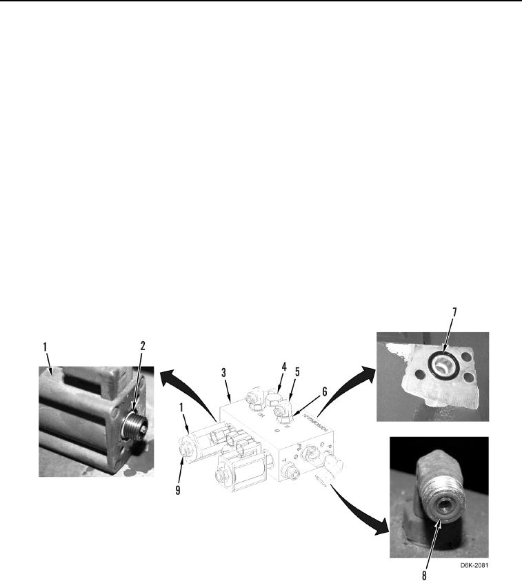
1. Remove check valve (Figure 3, Item 4) from winch manifold (Figure 3, Item 3).
2. Loosen three fasteners (Figure 3, Item 9) and remove solenoids (Figure 3, Item 1) from winch manifold
(Figure 3, Item 3).
3. Remove three O-rings (Figure 3, Item 2) from fasteners (Figure 3, Item 9). Discard O-rings.
4. Remove three fasteners (Figure 3, Item 9) from solenoids (Figure 3, Item 1).
5. Loosen five nuts (Figure 3, Item 6) and remove fittings (Figure 3, Item 5) from winch manifold (Figure 3,
Item 3).
6. Remove five O-rings (Figure 3, Item 8) from fittings (Figure 3, Item 5). Discard O-rings.
7. Remove O-ring (Figure 3, Item 7) from bottom of winch manifold (Figure 3, Item 3). Discard O-ring.
Figure 3. Winch Manifold, Solenoids, O-rings, and Retaining Hardware.
0266
END OF TASK