
TM 5-2410-240-23-3
0284
ROPS/FOPS REMOVAL, INSTALLATION
000284
Removal
000284
Basic Issue Items (BII) include a set of three door storage brackets. Door storage brackets are stowed behind front
radiator lower grill and secured with knobs. Retrieve brackets before beginning this procedure. Reinstall knobs.
Removed doors are attached to storage brackets and, using wood supports, will be secured to shipping platform
along with ROPS/FOPS. Arrange two 36-in. long (91 cm) 4x4s parallel to each other, 36 in. (91 cm) apart, on
shipping platform.
Components that are removed for transport but that are too small to be tied down must be securely stored on the
machine.
1. Turn engine start switch to ON position (TM 5-2410-240-10). DO NOT start engine.
2. Activate left door wiper (TM 5-2410-240-10).
3. Turn engine start switch to OFF position when wiper is approximately parallel to ground. This positions the
wiper blade for safe stowage (TM 5-2410-240-10).
4. Turn battery disconnect switch OFF (TM 5-2410-240-10).
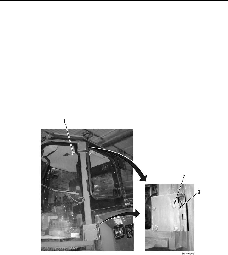
5. Remove eight bolts (Figure 10, Item 2) and two hinge cover plates (Figure 10, Item 3) from left door (Figure 10,
Item 1).
Figure 10. Hinge Cover Plates.
0284