
TM 5-2410-240-23-3
0284
ROPS/FOPS REMOVAL, INSTALLATION CONTINUED
WARN I N G
Use extreme caution when handling heavy parts. Provide adequate support and use
assistance during procedure. Failure to follow this warning may cause injury or death to
personnel.
N OT E
Door weighs approximately 60 lb (27 kg).
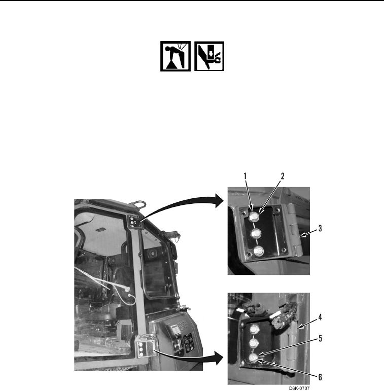
8. Remove three bolts (Figure 12, Item 1) and washers (Figure 12, Item 2) at upper hinge assembly (Figure 12,
Item 3).
Figure 12. Door Hinge Bolts.
0284
9. Remove three bolts (Figure 12, Item 6) and washers (Figure 12, Item 5) at lower hinge assembly (Figure 12,
Item 4), then unlatch and remove door from machine.
10. Position door with outside surface facing down on 4x4s.
11. Repeat steps 5 through 10 to remove right door from machine.
12. Secure doors together using removed hinge fasteners (Figure 13, Item 3) to attach C-shaped door storage
brackets (Figure 13, Item 2) at door hinge locations.