
TM 5-2410-241-23-1
0017
ECM UNABLE TO COMMUNICATE
00017
N OT E
This procedure is for non-communicating ECMs. The first steps will verify that the data link
circuit between diagnostic connector and ECM is not causing communication problem.
1. Turn engine start switch to OFF position (TM 5-2410-241-10).
2. Turn battery disconnect switch to OFF position (TM 5-2410-241-10).
3. Check ECM and Ignition Power and Ground (WP 0013)
4. Disconnect J1 connector from all modules connected to data link.
5. At each harness, connect a jumper wire between data link (+) (circuit 893-GN) and data link (-)
(circuit 892-BR).
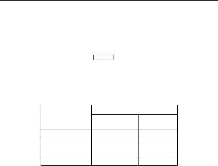
6. The following chart provides data link pin information for various ECM J1 connectors.
Table 1.
PIN NUMBER
ECM
Data Link (+)
Data Link (-)
Circuit 893 - GN
Circuit 892 - BR
Engine
9
8
Powertrain
10
20
Machine Monitoring
5
14
System
Messenger
6
5
0017-6