TM 5-2410-241-23-1
0017
ECM UNABLE TO COMMUNICATE CONTINUED
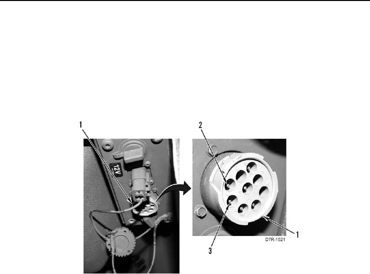
7. At diagnostic connector (Figure 5, Item 1), measure resistance between data link (+) pin D (Figure 5, Item 2)
circuit 893, and data link (-) pin E (Figure 5, Item 3) circuit 892.
If resistance is less than 5.0 ohms, circuit is OK. Remove jumper wire. Refer to appropriate work pack ge
a
for ECM replacement instructions. Return to this work package once ECM is replaced. Refer to Initializing
ECM.
If resistance is greater than 5.0 ohms, there is an o en or a poor connection in data link circuit. Check and
p
repair data link circuit, then try to establish communication with ECM. If ECM will still not communicate,
proceed to appropriate ECM Replacement work package. Return to this work package once ECM is
replaced. Refer to Initializing ECM in this work package.
Figure 5. Diagnostic Connector.
0017
END OF TASK
INITIALIZING ECM
00017
N OT E
Two key start ON/OFF cycles are required for correct initialization of new ECM.
1. Turn battery disconnect switch to ON position (TM 5-2410-241-10).
2. Turn engine start switch to ON position (TM 5-2410-241-10).
3. Wait one minute to allow ECM to initialize.
4. Turn engine start switch to OFF position (TM 5-2410-241-10).
5. Turn engine start switch to ON position (TM 5-2410-241-10).
a. Cat Mil ET will indicate whether ECM has been programmed or not.
b. If ECM is not programmed, program ECM using WinFlash software contained with Cat Mil ET. Proceed to
FLASH PROGRAMMING in this work package.
If ECM is programmed, Cat Mil ET will allow access to ECM to load configuration data. Proceed to Copy
c.
Configuration to ECM in this work package.
END OF TASK

