
TM 5-2410-241-23-1
0020
Table 1. Powertrain Troubleshooting Procedures - Continued.
0020
MALFUNCTION
TEST OR INSPECTION
CORRECTIVE ACTION
299-8 Transmission Lever
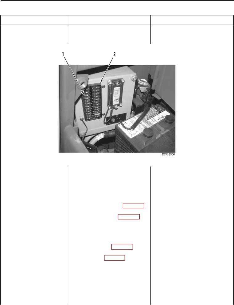
11. Remove Fuse # 5 (Figure 8,
Position Sensor Out of
Item 1) from fuse panel (Figure 8,
Range - Continued
Item 2) (TM 5-2410-241-10).
Figure 8. Fuse #5.
0020
12. Using a digital multimeter (WP
1. If continuity is found, install Fuse
0296), test for continuity between
#5 on fuse panel, and proceed to
blades of Fuse #5.
step 13.
2. If continuity is NOT found, replace
Fuse #5, and proceed to step 24.
13. Disconnect steering control har-
ness connector X-C1 (WP 0018,
Figure 34) from platform harness
connector MA-C14 (WP 0018,
Figure 33).
14. Using a digital multimeter (WP
1.
If continuity is found, proceed to
0296), test for continuity between
step 15.
pin 6 on steering control harness
2.
If continuity is NOT found, replace
connector X-C1 (WP 0018, Figure
steering control harness (WP
34) and pin 1 on FNR sensor con-
0178). Ensure all harness connec-
nector X-C8 (WP 0018, Figure 49).
tors are reconnected. Verify cor-
rect operation of machine (TM 5-
2410-241-10).