
TM 5-2410-241-23-1
0020
Table 1. Powertrain Troubleshooting Procedures - Continued.
0020
MALFUNCTION
TEST OR INSPECTION
CORRECTIVE ACTION
299-8 Transmission Lever
15. Disconnect platform harness con-
Position Sensor Out of
nector MA-C3 (WP 0018, Figure
Range - Continued
21) from fuse panel wiring harness
connector A-C1 (WP 0018, Figure
22).
16. Using a digital multimeter (WP
1.
If continuity is found, proceed to
0296), test for continuity between
step 17.
pin 3 on platform harness connec- 2.
If continuity is NOT found, replace
tor MA-C3 (WP 0018, Figure 21)
platform harness (WP 0209).
and pin 6 on platform harness con-
Ensure all harness connectors are
nector MA-C14 (WP 0018, Figure
reconnected. Verify correct opera-
33).
tion of machine (TM 5-2410-241-
10).
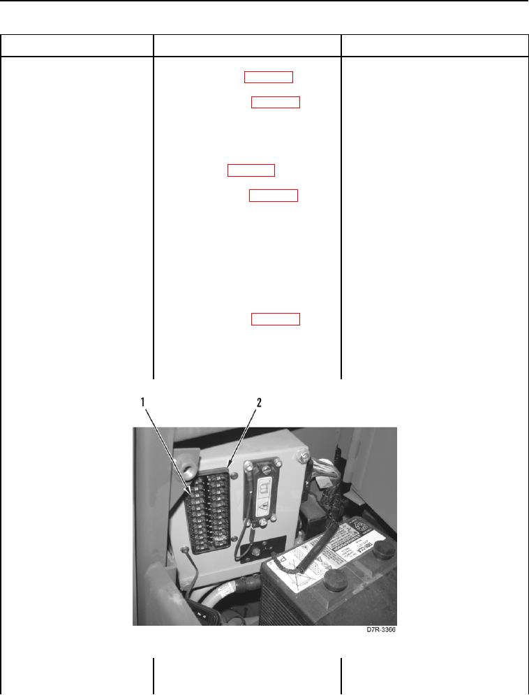
17. Remove ECM Fuse #5 (Figure 9,
Item 1) from fuse panel (Figure 9,
Item 2).
18. Using a digital multimeter (WP
1. If continuity is found, proceed to
0296), test for continuity between
step 19.
pin 3 on fuse panel wiring harness
2. If continuity is NOT found, replace
connector A-C1 (WP 0018, Figure
fuse panel wiring harness (WP
22) and left cavity of ECM Fuse #5
0176). Ensure all harness connec-
(Figure 9, Item 1) located in fuse
tors are reconnected. Verify cor-
panel (Figure 9, Item 2).
rect operation of machine (TM 5-
2410-241-10).
Figure 9. Fuse #5.
0020