
TM 5-2410-241-23-1
0020
Table 1. Powertrain Troubleshooting Procedures - Continued.
0020
MALFUNCTION
TEST OR INSPECTION
CORRECTIVE ACTION
1402-5 Transmission Sole-
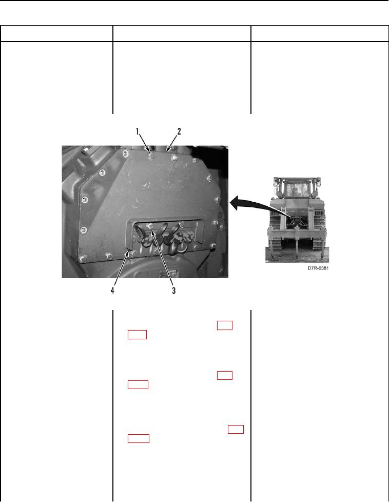
4. Remove two bolts (Figure 49,
noid Valve #2 Current
Item 3) and guard (Figure 49,
Below Normal - Contin-
Item 4) from machine.
ued
5. Remove 15 bolts (Figure 49,
Item 1) and plate (Figure 49,
Item 2) from machine
Figure 49. Guard, Plate, and Retaining Hardware.
0020
6. Disconnect transmission solenoid
valve #2 connector P-C3 (WP
0018, Figure 72) from transmis-
sion solenoid valve #2 (WP 0145).
7. Insert a jumper wire between pins
1 and 2 on transmission solenoid
valve #2 connector P-C3 (WP
0018, Figure 72).
8. Turn ignition switch and battery
disconnect switch to ON position
(TM 5-2410-241-10).
9. Check for Diagnostic Codes (WP
1. If active 1402-6 code is present,
replace transmission solenoid
valve #2 (WP 0145). Ensure all
harness connectors are recon-
nected. Verify correct operation of
machine (TM 5-2410-241-10).
2. If active 1402-5 code is present,
proceed to step 10.