
TM 5-2410-241-23-1
0035
STEERING HYDRAULIC CIRCUIT TESTS CONTINUED
00035
High Pressure Cutoff Test - Continued
00035
51. Ensure all implements are lowered to the ground (TM 5-2410-241-10).
52. Release hydraulic system pressure (WP 0186).
53. Turn ignition switch and battery disconnect switch to OFF position (TM 5-2410-241-10).
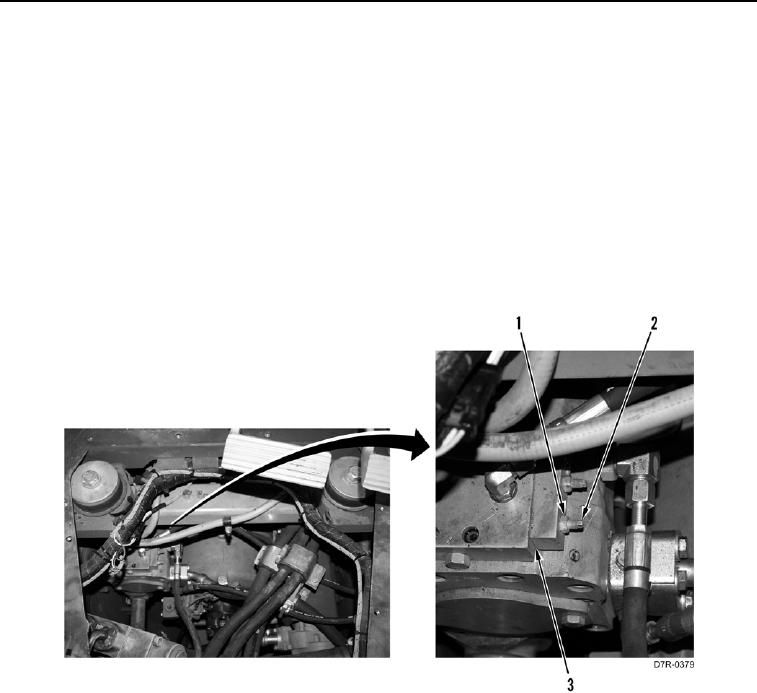
54. Hold adjustment screw (Figure 8, Item 2) and loosen nut (Figure 8, Item 1) on pump control valve (Figure 8,
Item 3).
55. If high pressure cutoff is high, turn adjustment screw (Figure 8, Item 2) counterclockwise to decrease margin
pressure.
56. If high pressure cutoff is low, turn adjustment screw (Figure 8, Item 2) clockwise to increase margin pressure.
57. Hold adjustment screw (Figure 8, Item 2) and tighten nut (Figure 8, Item 1) on pump control valve (Figure 8,
Item 3). Tighten nut to 144 lb-in. (16 Nm).
Figure 8. Pressure Compensator Adjustment.
035
0035-10