
TM 5-2410-241-23-1
0042
INSTALLATION CONTINUED
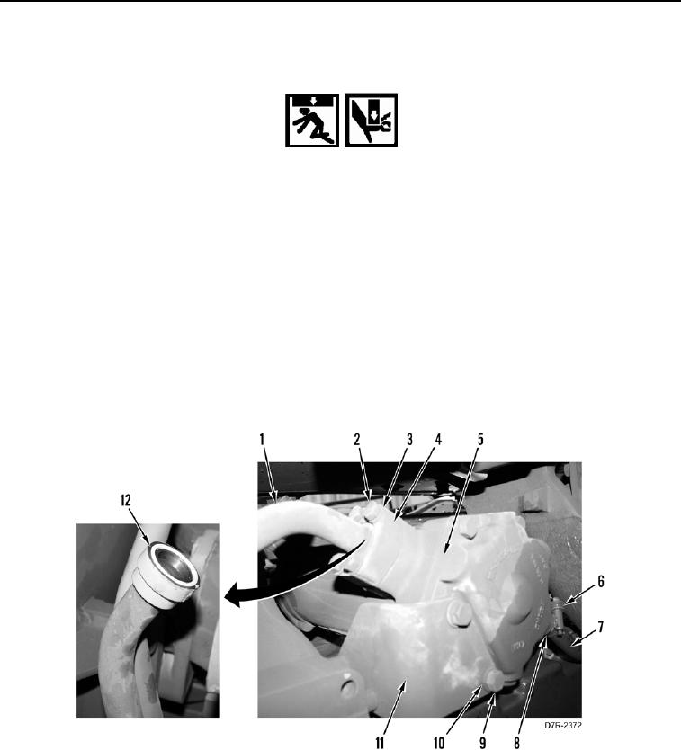
5. Install two new O-rings (Figure 5, Item 12) on lines (Figure 5, Item 1).
WARN I N G
Use extreme caution when handling heavy parts. Provide adequate support and use
assistance during procedure. Ensure lifting device used is in good condition and of
suitable load capacity. Keep clear of heavy parts supported only by lifting device. Failure to
follow this warning may cause injury or death to personnel.
N OT E
Transmission oil cooler weighs approximately 65 lb (29.5 kg).
6. With assistance, install transmission oil cooler (Figure 5, Item 5), two washers (Figure 5, Item 10) and bolts
(Figure 5, Item 9) on bracket (Figure 5, Item 11).
7. Install two lines (Figure 5, Item 1), clamp (Figure 5, Item 4), eight washers (Figure 5, Item 3) and bolts (Figure
5, Item 2) on transmission oil cooler (Figure 5, Item 5).
8. Connect hose (Figure 5, Item 7) with clamp (Figure 5, Item 6) to fitting (Figure 5, Item 8).
9. Tighten clamp (Figure 5, Item 6) on hose (Figure 5, Item 7).
Figure 5. Hose and Lines.
0042
END OF TASK