
TM 5-2410-241-23-1
0042
REMOVAL CONTINUED
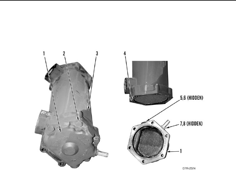
7. Remove four bolts (Figure 3, Item 2), bonnet (Figure 3, Item 1) and gasket (Figure 3, Item 4) from transmission
oil cooler (Figure 3, Item 3). Discard gasket.
8. Remove fitting (Figure 3, Item 7) and O-ring (Figure 3, Item 8) from bonnet (Figure 3, Item 1). Discard O-ring.
9. Remove plug (Figure 3, Item 5) and O-ring (Figure 3, Item 6) from bonnet (Figure 3, Item 1). Discard O-ring.
Figure 3. Transmission Oil Cooler Core.
0042
END OF TASK
CLEANING AND INSPECTION
00042
Clean and inspect all parts IAW Mechanical General Maintenance Instructions (WP 0295).
END OF TASK
INSTALLATION
00042
N OT E
Install hoses, lines and fittings as tagged during removal.
1. Install new O-ring (Figure 3, Item 6) and plug (Figure 3, Item 5) on bonnet (Figure 3, Item 1).
2. Install new O-ring (Figure 3, Item 8) and fitting (Figure 3, Item 7) on bonnet (Figure 3, Item 1).
3. Install new gasket (Figure 3, Item 4), bonnet (Figure 3, Item 1) and four bolts (Figure 3, Item 2) on transmission
oil cooler (Figure 3, Item 3).