
TM 5-2410-241-23-2
0122
REMOVAL CONTINUED
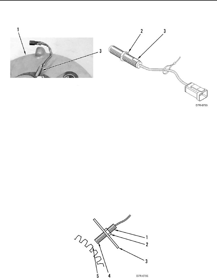
3. Loosen nut (Figure 2, Item 2) and remove sensor (Figure 2, Item 3) from housing (Figure 2, Item 1).
Figure 2. Converter Sensor.
0122
END OF TASK
CLEANING AND INSPECTION
000122
Clean and inspect all parts IAW Mechanical General Maintenance Instructions (WP 0295).
END OF TASK
INSTALLATION
000122
1. Center gear tooth (Figure 3, Item 5) to align with sensor (Figure 3, Item 1).
2. Install sensor (Figure 3, Item 1) until sensor tip (Figure 3, Item 4) touches gear tooth (Figure 3, Item 5).
3. Set gap between sensor tip (Figure 3, Item 4) and gear tooth (Figure 3, Item 5) by turning sensor (Figure 3,
Item 1) 180 degrees counterclockwise.
4. Hold sensor (Figure 3, Item 1) and tighten jam nut (Figure 3, Item 2) to 18 lb-ft (25 Nm) on housing (Figure 3,
Item 3). Refer to Torque Limits (WP 0298).
Figure 3. Sensor Adjustment.
0122