
6
TM 5-2410-241-23-2
FIELD MAINTENANCE
-
TORQUE CONVERTER RELIEF VALVE SERVICE
012
3
Removal, Cleaning and Inspection, Installation, Test and Adjustment
INITIAL SETUP
Tools and Special Tools
Materials/Parts - Continued
0
0
Tool Kit, General Mechanic's
5M-9623 SHIM (0.9-MM THK)
0
(WP 0302, Item 65)
0
References
0
Gauge, Pressure, Dial Indicating (5,800 psi)
WP 0295
0
(WP 0302, Item 29)
0
Gauge Kit, Pressure, Dial Indicating
Equipment Condition
0
(WP 0302, Item 28)
0
Machine parked (TM 5-2410-241-10)
0
Materials/Parts
0
Middle bottom guards removed (WP 0199)
0
Rag, Wiping (WP 0303, Item 24)
0
Front floor plate removed (WP 0230)
0
Tag, Marker (WP 0303, Item 34)
0
Drawing Required
0
Tiedown Strap (WP 0303, Item 36)
0
TM 5-2410-241-24P, Figure 52
0
O-ring (6)
0
Estimated Time to Complete
0
4.5 Hr
0
REMOVAL
000123
N OT E
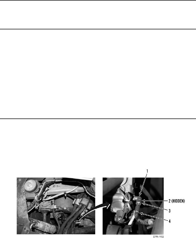
Tag and mark all hoses to aid installation.
1. Loosen tube nut (Figure 1, Item 3) and remove hose (Figure 1, Item 4) from fitting (Figure 1, Item 1).
2. Remove O-ring (Figure 1, Item 2) from fitting (Figure 1, Item 1). Discard O-ring.
Figure 1. Pressure Check Hose.
0123