
TM 5-2410-241-23-2
0123
INSTALLATION
000123
N OT E
Install fitting as noted during removal.
Install electrical connections as noted during removal.
1. Install new O-ring (Figure 2, Item 11) and fitting (Figure 2, Item 10) on torque converter outlet relief valve
(Figure 2, Item 5).
2. Install three new O-rings (Figure 2, Item 6) on torque converter outlet relief valve (Figure 2, Item 5).
3. Install torque converter outlet relief valve (Figure 2, Item 5), three clips (Figure 2, Item 3), washers (Figure 2,
Item 1) and bolts (Figure 2, Item 2) on machine.
4. Install line (Figure 2, Item 12), four washers (Figure 2, Item 14), and bolts (Figure 2, Item 13), on torque
converter output relief valve (Figure 2, Item 5).
N OT E
Install electrical connections and harness as noted during removal.
5. Position harness (Figure 2, Item 4) on machine.
6. Connect connector (Figure 2, Item 7) on temperature sensor (Figure 2, Item 9).
7. Install new tiedown straps (Figure 2, Item 8) on harness (Figure 2, Item 4).
N OT E
Install hoses as noted during.
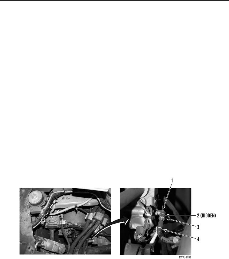
8. Install new O-ring (Figure 3, Item 2) on fitting (Figure 3, Item 1).
9. Install hose (Figure 3, Item 4) and tube nut (Figure 3, Item 3) on fitting (Figure 3, Item 1).
Figure 3. Pressure Check Hose.
0123
END OF TASK