
TM 5-2410-241-23-2
0123
TEST AND ADJUSTMENT
000123
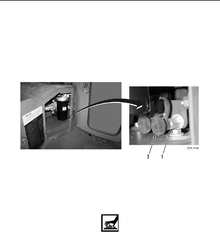
1. Remove cap (Figure 4, Item 2) from fitting (Figure 4, Item 1).
2. Install pressure gauge on fitting (Figure 4, Item 1).
3. Start engine. Powertrain oil must be at operating temperature.
4. With park brake disengaged and steering control lever in the NEUTRAL position, run engine at HIGH IDLE
(2100 RPM).
5. Pressure gauge should read 75 10 psi (515 70 kPa).
6. With park brake disengaged and steering control lever in the NEUTRAL position, run engine at LOW IDLE
(800 RPM).
7. Pressure gauge should read 55 10 psi (380 70 kPa).
Figure 4. Test Port.
0123
N OT E
One shim changes pressure setting by 2.4 psi (16.5 kPa). Adding shims will raise
pressure. Removing shims will lower pressure.
8. Park machine (TM 5-2410-241-10).
WARN I N G
Hot oil and hot components can cause injury. Do not allow hot oil or hot components to
contact skin. Failure to follow this warning may result in injury to personnel.
9. If the pressure is incorrect, adjust pressure by removing or adding shims (Figure 5, Item 11) as follows:
N OT E
Tag and mark all electrical connections.
a. Remove tiedown strap (Figure 5, Item 3) and disconnect connector (Figure 5, Item 4) from harness
(Figure 5, Item 2). Position harness aside.