
TM 5-2410-241-23-2
0123
REMOVAL CONTINUED
N OT E
Tag and mark all electrical connections to aid installation.
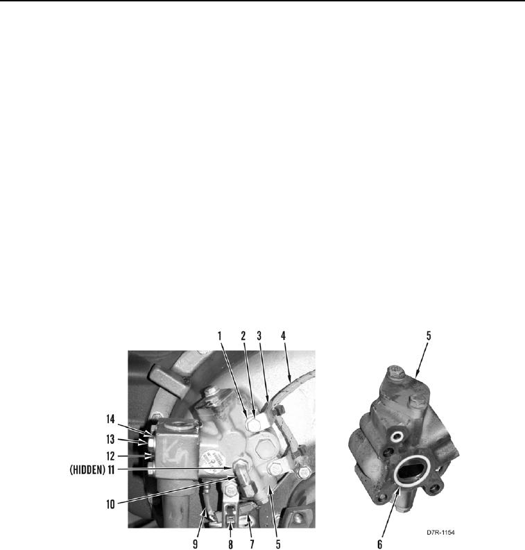
3. Remove tiedown straps (Figure 2, Item 8) from harness (Figure 2, Item 4). Discard tiedown straps.
4. Disconnect connector (Figure 2, Item 7) from temperature sensor (Figure 2, Item 9).
5. Position harness (Figure 2, Item 4) aside.
6. Remove four bolts (Figure 2, Item 13) and washers (Figure 2, Item 14) from line (Figure 2, Item 12).
7. Loosen line (Figure 2, Item 12) from torque converter output relief valve (Figure 2, Item 5).
8. Remove three bolts (Figure 2, Item 2), washers (Figure 2, Item 1), clips (Figure 2, Item 3), and torque converter
outlet relief valve (Figure 2, Item 5) from machine.
9. Remove three O-rings (Figure 2, Item 6) from torque converter outlet relief valve (Figure 2, Item 5) and line
(Figure 2, Item 12). Discard O-rings.
N OT E
Note position and orientation of fitting to aid installation.
10. Remove fitting (Figure 2, Item 10) and O-ring (Figure 2, Item 11) from torque converter outlet relief valve
(Figure 2, Item 5). Discard O-ring.
Figure 2. Torque Converter Output Relief Valve.
0123
END OF TASK
CLEANING AND INSPECTION
000123
Clean and inspect all parts IAW Mechanical General Maintenance Instructions (WP 0295).
END OF TASK