
TM 5-2410-241-23-2
0127
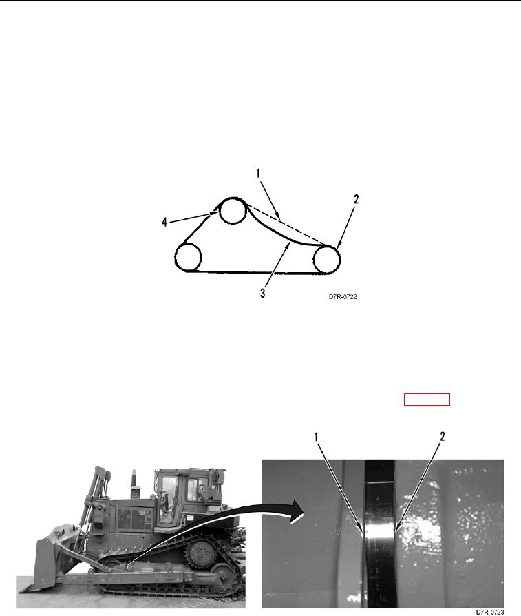
TRACK TENSION MEASUREMENT
000127
1. Move machine forward. Allow the machine to stop without use of brakes.
2. Install string (Figure 12, Item 1) on track (Figure 12, Item 3) near sprocket segment (Figure 12, Item 4).
3. Install other end of string (Figure 12, Item 1) on track (Figure 12, Item 3) near front idler (Figure 12, Item 2).
String should be tight.
4. Measure from track shoe tip (Figure 12, Item 3) to string (Figure 12, Item 1) at lowest point. Correct adjustment
is 4.5 in. (115 mm).
5. Loosen or tighten track to meet specification.
Figure 12. Track Adjustment.
0127
END OF TASK
LOOSE TRACK ADJUSTMENT
000127
1. Measure between points on front track roller frame (Figure 13, Item 1) and rear track roller frame (Figure 13,
Item 2). If measurement is over 5.4 in. (138 mm) do not adjust. Replace track chain (WP 0129).
Figure 13. Loose Track.
0127