
TM 5-2410-241-23-2
0127
INSTALLATION CONTINUED
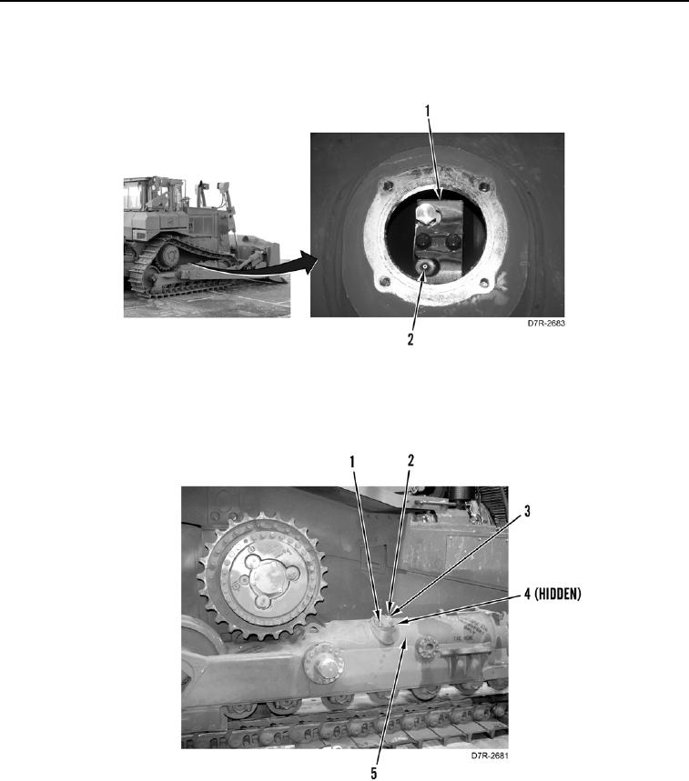
16. Add grease through valve (Figure 10, Item 2) on track adjuster (Figure 10, Item 1) until track is at specification
of 4.5 in. (115 mm).
Figure 10. Track Tension Adjustment.
0127
17. Install new O-ring (Figure 11, Item 4), cap (Figure 11, Item 1), four washers (Figure 11, Item 3), and bolts
(Figure 11, Item 2) on adjuster (Figure 11, Item 5).
Figure 11. Adjuster Cap.
0127
END OF TASK