
TM 5-2410-241-23-2
0147
REMOVAL
000147
N OT E
Tag harness to aid installation.
Clean exterior of component to prevent contamination.
Plug all lines, hoses and tubes to prevent contamination and leaks.
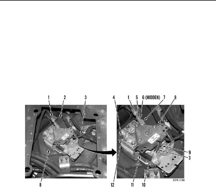
1. Remove tiedown straps (Figure 1, Item 9) and disconnect three connectors (Figure 1, Item 10) from three
solenoid valve connectors (Figure 1, Item 11). Position three harnesses (Figure 1, Item 3) aside from control
valve (Figure 1, Item 8).
2. Loosen tube nut (Figure 1, Item 5) and remove hose (Figure 1, Item 1) from fitting (Figure 1, Item 7).
3. Remove fitting (Figure 1, Item 7) and two O-rings (Figure 1, Item 6) from control valve (Figure 1, Item 8).
4. Remove four bolts (Figure 1, Item 4), washers (Figure 1, Item 12), and control valve (Figure 1, Item 8) from
chassis (Figure 1, Item 2).
Figure 1. Control Valve Harness.
0147