
TM 5-2410-241-23-2
0147
REMOVAL CONTINUED
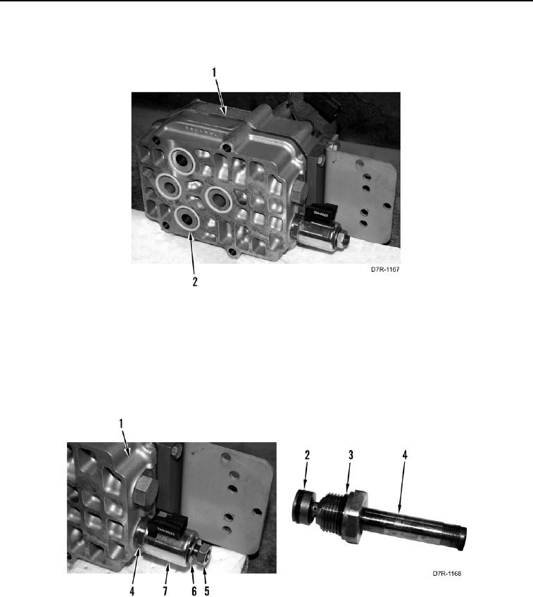
5. Remove four O-rings (Figure 2, Item 2) from control valve (Figure 2, Item 1). Discard O-rings.
Figure 2. Control Valve Seals.
0147
6. Remove nut (Figure 3, Item 5), washer (Figure 3, Item 6), and coil (Figure 3, Item 7) from spool assembly
(Figure 3, Item 4).
7. Remove spool assembly (Figure 3, Item 4) from manifold (Figure 3, Item 1).
8. Remove O-rings (Figure 3, Item 2) and O-ring (Figure 3, Item 3) from spool assembly (Figure 3, Item 4).
Discard O-rings.
Figure 3. Solenoid Valve.
0147