
TM 5-2410-241-23-2
0159
JUNCTION BLOCK TO FUSE PANEL POWER CABLE REMOVAL CONTINUED
N OT E
Note cable routing to aid installation.
Tag and mark all electrical connections to aid installation.
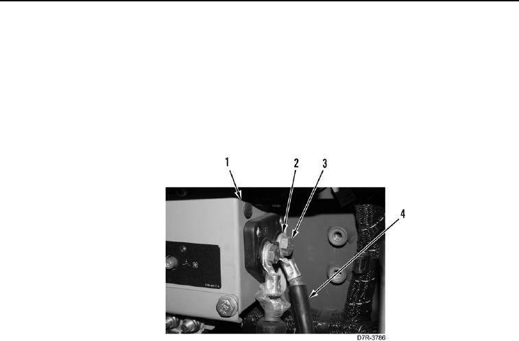
5. Remove bolt (Figure 6, Item 3), washers (Figure 6, Item 2) and positive battery cable (Figure 6, Item 4) from
fuse panel (Figure 6, Item 1).
6. Position positive battery cable (Figure 6, Item 4) aside.
Figure 6. Fuse Panel Cable.
0159