
TM 5-2410-241-23-2
0184
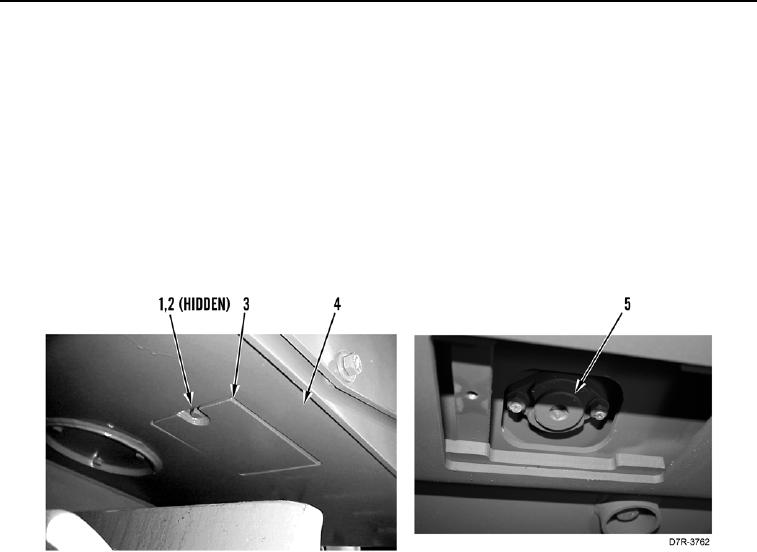
HYDRAULIC SYSTEM OIL CHANGE CONTINUED
7. Remove bolt (Figure 2, Item 1), washer (Figure 2, Item 2) and plate (Figure 2, Item 3) from hull (Figure 2,
Item 4).
8. Remove drain plug (Figure 2, Item 5) and attach hose to a 126-7914 swivel. Install swivel and hose into drain
plug opening. A pipe nipple 4 inch (10 cm) and a hose can also be used. Use a 1 inch (25.4 mm) pipe with 1/2
inch NPTF threads. Do not tighten pipe.
9. Rotate swivel clockwise to open internal drain valve. Allow oil to drain into suitable container.
10. Remove swivel from drain plug opening. Internal drain valve will close.
11. Clean drain plug and install drain plug (Figure 2, Item 5). Tighten drain plug to a torque of 50 5 lb-ft (68 7
Nm).
12. Install plate (Figure 2, Item 3), washer (Figure 2, Item 2) and bolt (Figure 2, Item 1) on hull (Figure 2, Item 4).
Figure 2. Hydraulic System Oil Drain.
0184
13. Install filler strainer (Figure 1, Item 5) in oil filler tube (Figure 1, Item 3).
14. Refer to LO 5-2410-241-13 to determine correct amount and type of hydraulic oil to fill hydraulic oil tank. Fill
hydraulic oil tank. Maintain oil level to FULL mark in sight gauge. Check with attachments on ground and with
cold oil.
15. Start engine. Run engine (TM 5-2410-241-10).
16. Maintain oil level to FULL mark in sight gauge.
17. Install hydraulic tank filler cap (Figure 1, Item 1).
18. Stop engine (TM 5-2410-241-10).
END OF TASK
END OF WORK PACKAGE