
TM 5-2410-241-23-2
0193
REMOVAL CONTINUED
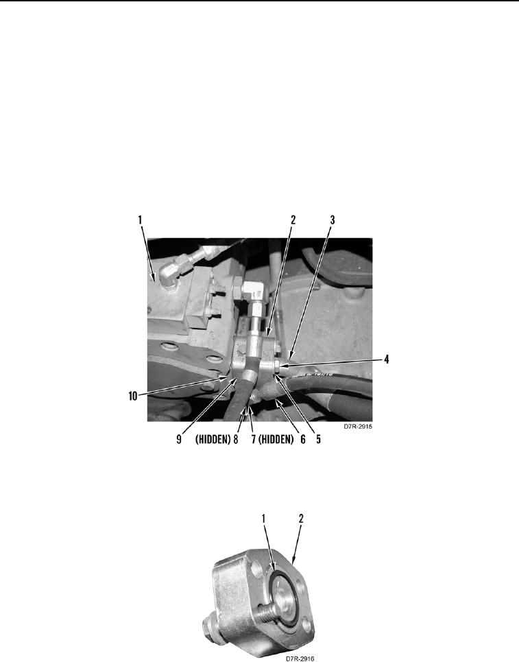
1. Remove four bolts (Figure 1, Item 4) and washers (Figure 1, Item 5) from flange (Figure 1, Item 2).
2. Disconnect hose (Figure 1, Item 3) and flange (Figure 1, Item 2) from spacer (Figure 1, Item 9).
3. Disconnect pilot accumulator hose (Figure 1, Item 6) from elbow (Figure 1, Item 7).
4. Remove spacer (Figure 1, Item 9) and seal (Figure 1, Item 10) from implement pump (Figure 1, Item 1).
Discard seal.
N OT E
Note position and orientation of elbow to aid installation.
5. Remove elbow (Figure 1, Item 7) from spacer (Figure 1, Item 9).
6. Remove two O-rings (Figure 1, Item 8) from elbow (Figure 1, Item 7). Discard O-rings.
Figure 1. Implement Pump to Main Hydraulic Control Valve.
0193
7. Remove O-ring (Figure 2, Item 1) from hose (Figure 2, Item 2). Discard O-ring.
Figure 2. Flange.
0193