
TM 5-2410-241-23-2
0193
INSTALLATION CONTINUED
N OT E
Install elbow as noted during removal.
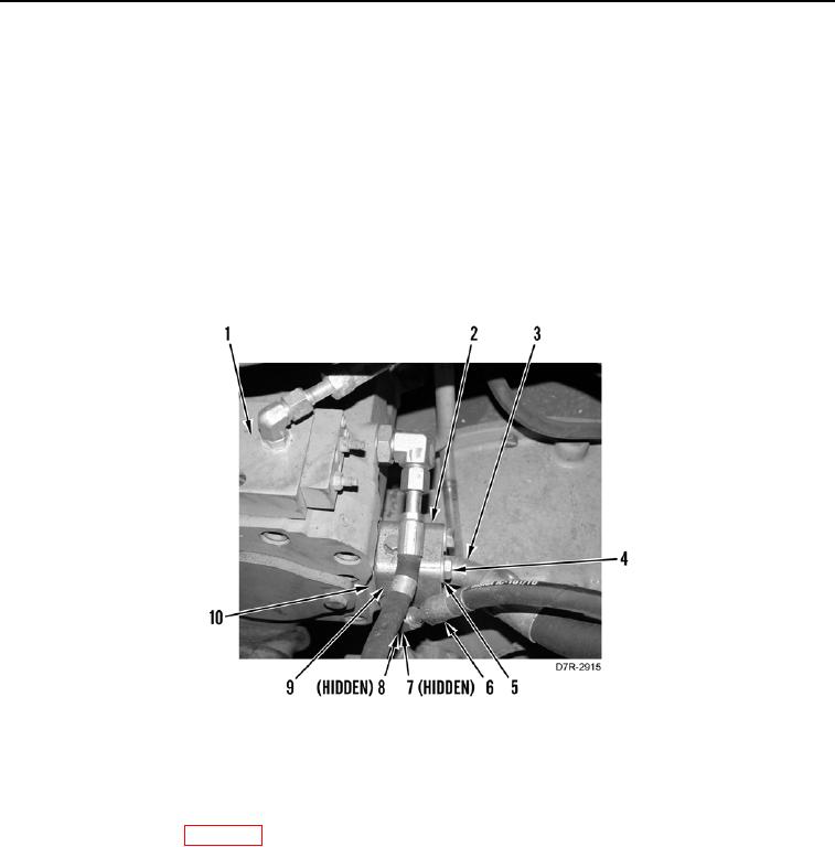
7. Install two new O-rings (Figure 5, Item 8) on elbow (Figure 5, Item 7).
8. Install elbow (Figure 5, Item 7) on spacer (Figure 5, Item 9).
9. Install new seal (Figure 5, Item 10) and spacer (Figure 5, Item 9) on implement pump (Figure 5, Item 1).
10. Connect hose (Figure 5, Item 3) and two pipe flange (Figure 5, Item 2) on spacer (Figure 5, Item 9).
11. Install four washers (Figure 5, Item 5) and bolts (Figure 5 Item 4) on flange (Figure 5, Item 2).
12. Install pilot accumulator hose (Figure 5, Item 6) on elbow (Figure 5, Item 7).
Figure 5. Implement Pump to Main Hydraulic Control Valve.
0193
END OF TASK
FOLLOW-ON TASKS
000193
1. Fill hydraulic system (WP 0184).
2. Install front and rear floor plates (WP 0230).
3. Install right platform access panels (WP 0208).
END OF TASK
END OF WORK PACKAGE